What is PLC? How does it work? (Very practical PLC )
Very practical PLC
Are you from an Engineering background?
Have you persuing or completed the Instrumentation and Control, Electrical, Electronics or Electronics and Communication branch of Engineering?
If yes, then you might be interested to know about the Programmable Logic Controller. You might have many questions in your mind such as What is PLC explain? What is PLC, and how it works? What is PLC and why it is used? What are the types of PLC? What are the main components of the PLC? Then in this article, you will be getting answers to all the above questions.
In this modern era of industry, PLC is the key to handle the complex control system. PLC has many advantages over old electromechanical relay systems. In simple words, we can say that PLC offers a simple solution to modify the complex operation of a control system without much disturbing the control wiring.
Now the questions are What is PLC or Programmable Logic Controller? How does it work? Why it is so important?
Programmable Logic Controller is the short abbreviation of PLC.
In this blog, I am going to cover detailed information about the PLC. By the end of this blog, you know What is PLC?, the Working of PLC, the Advantages, and disadvantages of PLC, Applications of PLC, etc.
What is PLC or Programmable Logic Controller?
The programmable logic controller is defined by Wikipedia,
“A programmable logic controller (PLC) is an industrial digital computer that has been ruggedized and adapted for the control of manufacturing processes or any activity that requires high-reliability control and ease of programming and process fault diagnosis.”
Have you got the definition or still confused, don’t worry I will be covering all the information in detail.
Simple Definition of PLC:
“Programmable Logic Controller (PLC) is an industrial computer used to control a specific process, machine system or sometimes even an entire production line.”
Basic Overview of PLC:
PLC is an industrial computer without a mouse, keyboard, and monitor.
As it is an industrial computer, a logical program to control the process is prepared in the general computer.
Then this program is transferred to the PLC using cables. This program is stored in the PLC memory.
The logical program is prepared using a programming language called Ladder logic, Statement List, or Functional block diagram.
A program is prepared in such a way that people with electrical or instrumentation backgrounds can easily understand.
A Programmable Logic Controller consists of various inputs and outputs terminal.
A PLC monitors the status of switches and sensors using input terminals and based on this status they will give the command to the output devices through the output terminals.
PLC Architecture:
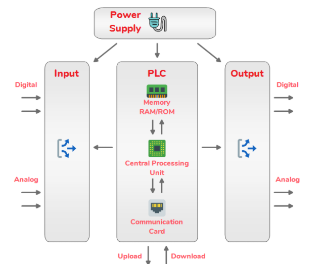
PLC Architecture
The above figure shows the basic architecture of the PLC system. These are the important components of the PLC system:
- Central Processing Unit
- Processor
- Memory
- Power Supply
- Input/Output Module
- Communication Protocol
- Programming Device
CPU (Central Processing Unit)
Central Processing Unit, we can say that this is the brain of this system. The program in the form of logical instructions is stored in the CPU.
All the arithmetic and logical functions are performed in the CPU. It executes the instructions as per the stored program by the user.
CPU consists of three subparts:
- Processor
- Memory
- Power Supply
The Processor in the CPU is used to do computations like managing the computer’s memory, monitoring the status of inputs, and activating output according to the user’s logical instructions.
The Memory in the CPU is used to store programs and data from the different equipment connected to PLC.
The PLC system mostly works with 24V DC voltage, Power Supply module is used to gives the appropriate voltage to a different module as well as the CPU of the PLC system.
Input/Output Module
Input/Output Module is the section of the PLC system in which all the field devices are connected.
All the field devices are connected with the PLC system are either Inputs or Outputs.
Inputs are the devices that supply a signal or data to the PLC.
There are many examples of inputs like a push button, toggle switch, safety switch, measurement devices, etc.
Outputs are the devices that await a signal or data from the PLC.
Like lights, motors, hooters, valves are the example of outputs.
Inputs and Outputs are of two types: Digital or Analog.
Digital Inputs/Outputs have only two-state. Whether it is ON or OFF. As a result, they only send/receive signals in the form of 0s or 1s to/from the PLC system.
Push-button, Toggle Switch, Safety switch, Relay contacts, etc. are examples of Digital inputs.
Lights, Hooters, Motors, Solenoid Valve, etc are examples of Digital outputs.
Analog Inputs/Outputs are once they have more than two states. These devices send/receive complex signals to/from the PLC system which is in the form of Voltage or Current.
For example, RTD (temperature detector) has more than two states, like the temp just not only hot or cold. It may be 30, 36, 40, 51, or an infinite number of states.
In the same way Pressure sensors, level sensors, etc are examples of Analog inputs.
Control Valve is the most common example of Analog Output, like it maybe 0%, 15%, 25%, 50%, 90% open.
Analog IOs
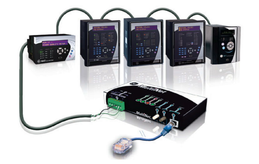
Communication Protocol
Communication Protocol is used to exchange data between PLC and connected devices. These are the most popular communication protocols used in the PLC system,
- Ethernet
- Profibus
- RS-232
- RS-485
- Multi-Point Interface (MPI)
- Point to Point (PPI)
- Data Highway (DH)
- Control Net
- Device Net
- USB Adapter
- PC Adapter
PLC Programming
User needs to download the program to control the processes. This program is stored in the CPU.
The program is prepared using a language which is called programming language. This is the list of PLC programming language:
- Ladder Diagram(LD)
- Instruction List(IL)
- Structured Text(ST)
- Function Block Diagram(FBD)
- Sequential Function Charts(SFC)
Out of all these languages, Ladder Diagram(LD) is widely used in the Automation industry because of its easy understanding.
How does PLC work?
PLC system has some instructions through which a user can make a logic depending on how they want to control the process.
These instructions are simple bit logic, comparison, timer, and counter, mathematical, etc.
Some basic skills are required to understand and create a control program.
There are mainly three steps to control the process in the PLC
- Monitor the status of inputs
- Execute the control program
- Update the status of outputs
Since PLC is a dedicated controller. It executes this program again and again. It took very little time to execute this cycle once and this time is called scan time. This scan time is very less, usually in mS.
All the inputs and outputs status must be stored in the memory section of the PLC. The memory section also stores complex information like mathematical calculation answers, scaling of analog inputs, and outputs other complex information.
No matter how many inputs and outputs you add, every PLC does the same three things,
- Monitors the input status
- Execute the program
- Updates the output status according to use logic.
What are a scan cycle and a scan time?
Each PLC has a scan time and a scan cycle. This considers how fast PLC work.
The Scan cycle is the cycle in which the PLC sens the inputs, executes the PLC programs, and then updates the outputs. This will take some amount of time usually in milliseconds.
The amount of time it takes for the PLC to finish one complete cycle is called the scan time of PLC.
Types of PLC
There are mainly two types of PLC in terms of physical hardware:
- Compact PLC or Fixed PLC
- Modular PLC
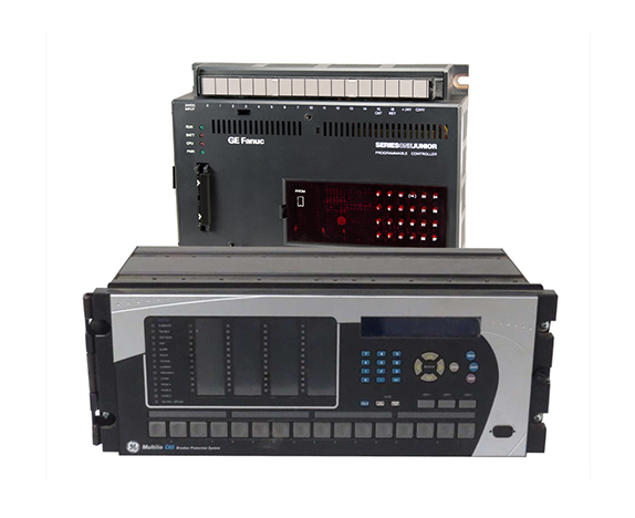
What is a Compact PLC?
All the modules are within a single case. This type of PLC has a fixed number of Input/Output modules.
The power supply, CPU and communication card are within a single case. From the below image you can get some ideas about the compact or fixed plc.
Compact OR Fixed PLC
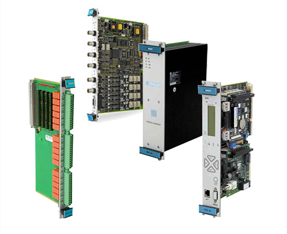
What is a Modular PLC?
The name itself suggests that this type of PLC consists of various modules. Inputs and Outputs modules can be easily expanded just by adding the modules.
All the modules are fitted in the rack, that’s why it is also called rack mounted PLC. The below image shows the modular type PLC.
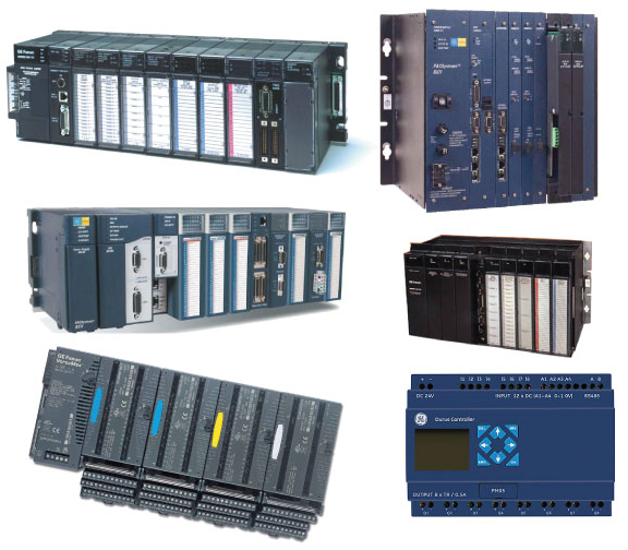
Modular PLC
Most Popular PLC Brands
There are multiple brands available for PLC system nowadays, but most popular are as below:
- Siemens
- Allen Bradley
- ABB
- GE
- Delta
- Mitsubishi
- Omron
- Schneider
Siemens is the highest used brand in the Automation industry.
Advantages and Disadvantages of PLC
Advantages:
Before PLC is introduced, a Relay is used to control the process. This relay control panel is required regular maintenance, it consumed a lot more power, and even during the troubleshooting time, it requires a lot of effort to find the problem because there are lots of wires and it takes too much time to figure it out.
There are some advantages of PLC over Relay control system:
- PLC system is easier to install and maintain(There are fewer wires in this system as compared to the Relay control system).
- Easy to program and modify the logic offline as well as online(Luckily, there is no need to change in wiring of the PLC system during modification of a process).
- PLC system requires negligible maintenance (There is only a computer used to upload/download the program as well as no moving contact is there).
- Easy troubleshooting, Saves a lot of time during troubleshooting(It’s very easy to troubleshoot in this system just by monitoring the program status via the programming software).
- PLC has a fast operating time usually in milliseconds.
Disadvantages:
- There are limitations of working PLCs under high temperature, vibration conditions.
- High Initial Cost (PLC is not considered necessary when applied to industrial systems that do not need to change the wiring)
Application of PLC
PLCs are widely used in almost all types of industries because of their rugged nature, flexibility, and reliability.
Here are some examples in which you can easily find the PLC
Domestic and Commercial applications
- Water level control in a tank
- Automatic car washing system
- Traffic control system
- Building system
- Elevator system
- Automatic doors
- Roller coasters
Industrial Applications
- Automatic operation and control of the air compressor system
- Bottle and liquid filling industry
- Automatic temperature control
- Belt conveyor system
- Energy monitoring system
- Production line control
- Raw material handling
Some of the industry types in which PLC can be widely used,
- Petrochemical
- Oil and Gas
- Steel
- Power Plant
- Food Manufacturing
- Automative
- Cement Industry
- Paper Industry
- Glass Manufacturing
- Raw Material Handling Industry
Final Thoughts
These are all the basic information about What is PLC?
Programmable Logic Controller is now common for the industrial automation sector and used in most applications. The basic skills of PLC are valuable. You will find more detailed information in future blogs.
PLC Tutorials:
- Sinking and Sourcing Circuits.
- Logic Gates using PLC Ladder logic.
- PLC Programming Examples | Bit Logic Instructions-Tutorial
- 5 different types of PLC programming languages.
- Electrical motor starter with a PLC program.
Automation Tutorials:
- What is SCADA Software? Overview, Features, Application of SCADA Software.
- Top 5 Advantages of a Distributed Control System, You Need to Know!
www.plc-module.com
XiongBa industrial control,PLC-Module,Automation,DCS System
Small editor:Panda